Automation project
Programming a Pick&Place robot with a Siemens PLC


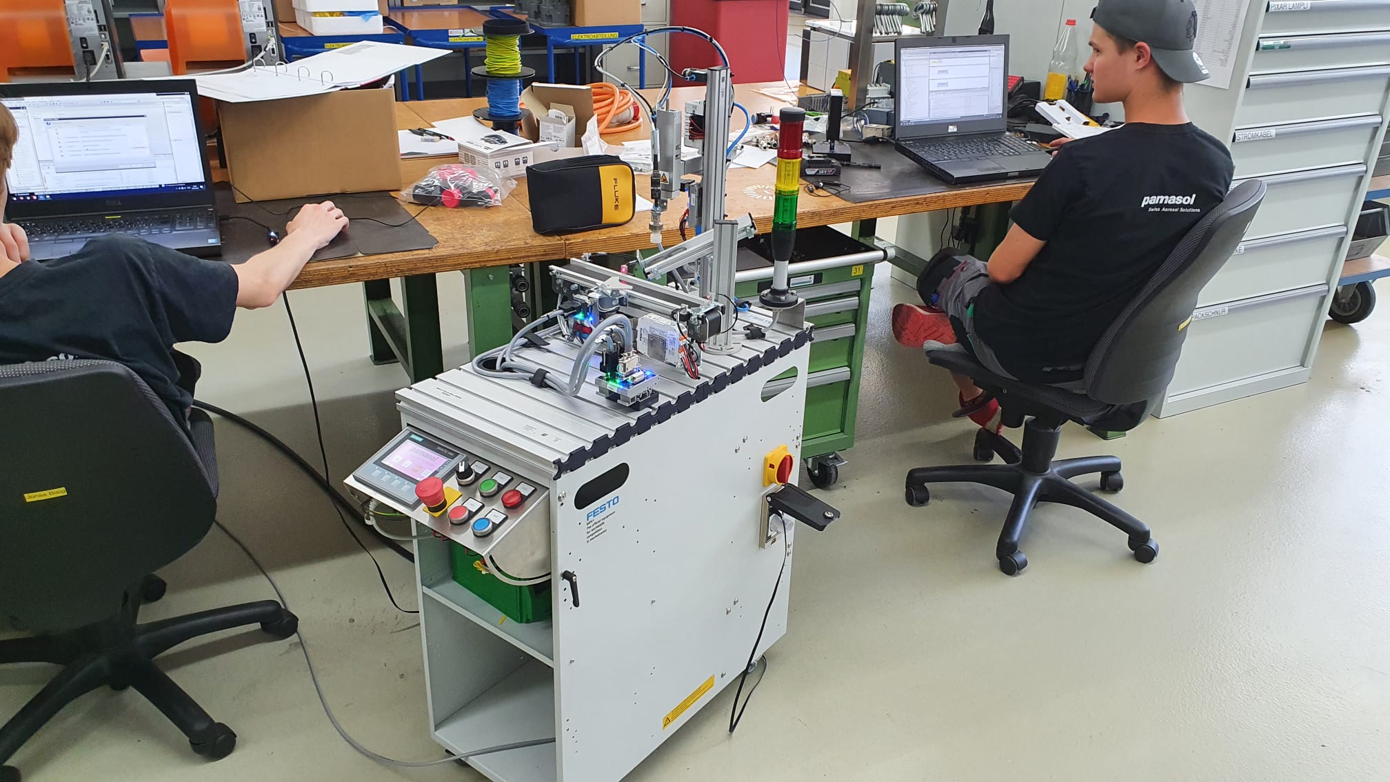
Aside from vocational school, inter-company professional training at Swissmechanic and practical work on aerosol machines for customers around the world, automation engineer apprentices at Pamasol also work on projects which focus on specific parts of the education.
The Pick&Place robot represents the PLC automation project of the education. It consists of a pneumatic claw from Festo Didactic.
The robot is controlled by a Siemens ET200SP PLC (programmable logic controller). The PLC is programmed with the Siemens TIA Portal, where you can choose between the following coding languages:
- Instruction list IL
- Ladder logic
- Function block diagram FBD
- Structured Control Language SCL
- S7 graph AS
The apprentices create with the help of YoutTube Videos a PLC program including the visualization of a touch panel. The program places lids on containers, similarly like the aerosol machines at Pamasol. Here spray cans get assembled with a valve, spray button or a cap.
Subsections of Automation project
Definition of task
Desrciption of process flow


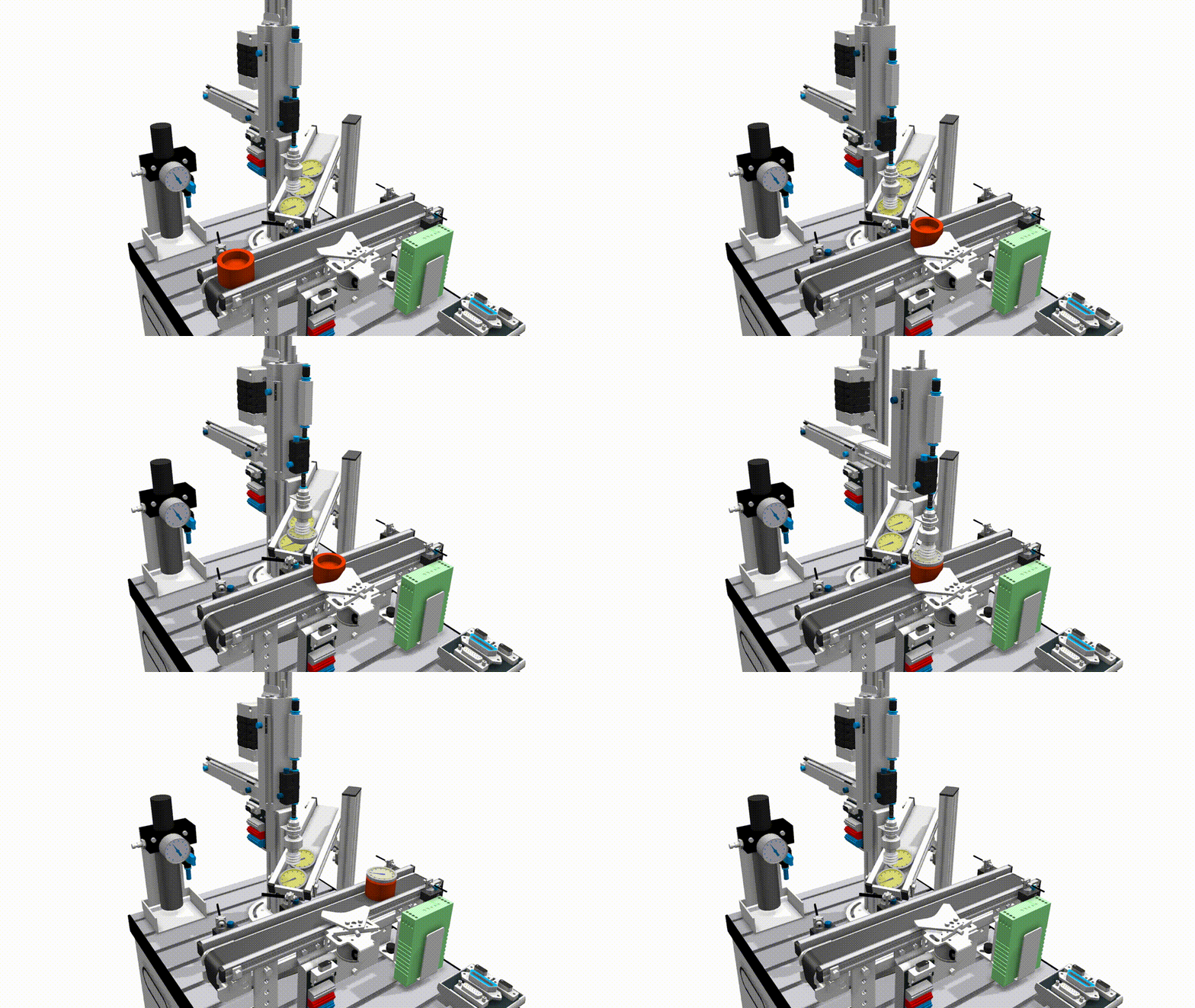
As shown in the animation above, the Pick&Placer should be programmed as follows, including the visualization of the touch panel.
- At first the Pick&Placer is retracted and the conveyor is not running
- The operator places a container on the conveyor at the inlet light barrier 100BG1 and presses the button Start.
- The container gets transported to the separator and stops there
- The Pick&Placer moves down, sucks a lid from the magazine, moves up and to the front and down again on top of the container.
- The vacuum gets released and as such places the lid on the container.
- The Pick&Placer moves to the start position.
- The separator lets the container with the placed lid move ahead.
- As sson as the container reaches the light barrier 100BG3, the conveyor stops.
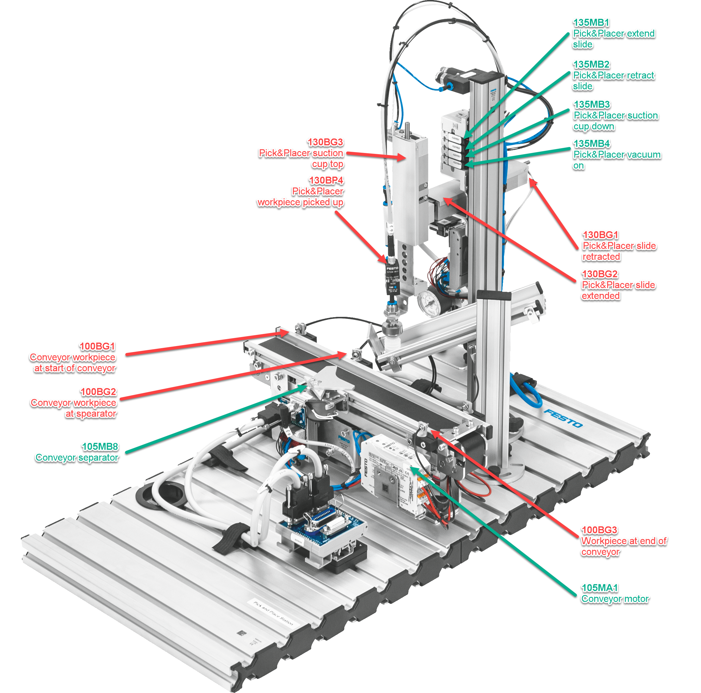
The positions of the most relevant sensors are shown below:


Info
The electrical diagram of the control cabinet can be downloaded here as a PDF
Documentation
The projects with all the comments can be downloaded as a TIA archive file (*.zap16, *.zap17 etc.) from the following file.
| Name | Date | Profession | Program |
|---|
| Stefan Feier | 2019-2023 | automation engineer | |
| Nicolas Diethelm | 2020-2024 | automation engineer | Download ZAP16 |
| Flavio Knobel | 2020-2024 | automation engineer | Download ZAP16 |
| Kevin Kälin | 2021-2025 | automation engineer | |
| Linus Lacher | 2022-2026 | automation engineer | |
Brief overview TIA V16
How the development environment TIA Portal is structured
To program a PLC, you need a laptop which has the PLC programming software - in technical jargon development environment - installed.
The Pick&Place robot is equipped with a Siemens PLC which is programmed with the development environment TIA Portal. TIA is short for «Totally Integrated Automation». More information regarding this software can be found on the Siemens website.
The video explains the user interface with the views Portal view and Project view. Additionally it explains the use of the online help.
Create a new project
The PLC hardware configuration as a basis
As a first step a new PLC project will be created in the projec view. Afterwards you need to project the installed PLC from the control cabinet in the software. This will be done with the hardware configuration.
The Pick&Place robot is equipped with a SIMATIC ET200 CPU. Additionally input and ouptut modules will be added and configured.
Articel no° of the CPU for the hardware config
- Control CPU 1512SP F-1 PN:
6ES7512-1SK01-0AB0 - Safety input ET200SP F-DI 8x 24V DC HF:
6ES7136-6BA00-0CA0 - Safety output ET200SP F-DQ 8x 24V DC/0.5A PP
6ES7136-6DC00-0CA0 - Digital input ET200SP DI 16x 24V DC ST:
6ES7131-6BH01-0BA0 - Digital output ET200SP DQ 16x 24V DC/0.5A ST:
6ES7132-6BH01-0BA0 - Analog input ET200SP AI 2x U/I 2/4-Wire HS:
6ES7134-6HB00-0DA1 - Analog output ET 200SP AQ 2xU ST:
6ES7135-6FB00-0BA1
Set module parameters
Configuring central processing unit (CPU) und IOs
The modules in the device configuration are named identically as the ones in the electrical diagram. Afterwards, the address range can be assigned in the property window. Alternatively, you can open the view Device view > Device overview. All modules and address ranges are listed in table here.
The BaseUnits of the input and output modules come in light gray and dark gray. The light gray modules are powered with 24VDC. Dark grey modules can’t be powered, they are bridged to the module to the left. The following BaseUnits are used in the project:
The absolute addressing uses the direct operand (i.e. I0.0), whereas the symbolic addressing utilizes a symbol name as a substitute for the operand (i.e. CC_TB_24MainOk).
- CC stands for control cabinet. This defines the place where the part is installed.
- TB stands for the electrical part in accordance to EN 81346. In this case it is the auxiliary contact of the power supply
10TB1 - 24MainOk stands for the abbreviation of the function in Upper Camel Case. In this case it is “24VDC power supply OK”.
The variables can be added and edited in the project navigation under Devices > PLC variables. The video additionally mentions the function for importing and exporting Excel files.
Tip
The Excel file, which can be used to import the PLC tags, can be downloaded here
Set HMI parameters
4 inch touch panel Siemens KTP400 Comfort
HMI stands for Human-Machine Interface. This is the touch panel, with which the operator controls the machine.
Add the HMI under Devices > Devices and networks. It is the KTP400 Comfort panel from Siemens with the type number 6AV2124-2DC01-0AX0.
Profinet stands for Process Field Network. It is a common protocol in the industry which uses TCP/IP Standards As such, the communication between PLC and HMI works similar to the internet (IP stands for Internet Protocol). Each member of the network gets a unique IP address - the Profinet address. Each address in the projetc can only show up once.
- Profinet address HMI 155PH1:
192.168.10.5 - Profinet address PLC 20KF3:
192.168.10.10
PLC simulation
Emulate CPU and HMI for tests without hardware
With the help of SIMATIC S7-PLCSIM the Pick&Place control can be simulated and tested without any hardware components added.
The video shows the simulation of the PLC and the touch panel. Emulating means recreating the functions of a computer with another device.
To be able to emulate a PLC or an HMI, you need to select the component in the Project navigator under Devices and click on the icon Start simulation in the smybol menu.
Afterwards the preferred blocks get loaded. These can be tested almost in the same fashion as with a hardware-based PLC. For example with the Monitor on/off function or with a SIM table.
Not that important here, but for other projects: You can’t load protected blocks in the simulation. If they exist in your project, you first need to enable the access for them.
Load program
Download program from PC to PLC and HMI
To load the program from the TIA portal into the PLC. In a first step, click under devices on Devices & networks, where you can display the IP addresses.
- CPU 1512SP F-1 PN:
192.168.10.10 - Touch panel KTP400 Comfort:
192.168.10.5
In a second step you need to give the laptop, which is in the same network, a static IP address. In Windows in the adapter options choose the address 192.168.10.99 for the Ethernet port.
Select the symbol Load in device in the toolbar to load the program in the PLC.
Since we are using a Safety Integrated PLC, both safety modules 20KF5 (inputs) and 20KF6 (outputs) need to be identified. You need to assign a Profisafe address.
On the HMI, click Settings > Transfer > PN/IE > Properties… > PN_X1 > Specify an IP Address > 192.168.10.5 to set the IP address. Additionally you need to click on Load in device.
Create program
First program for Pick&Place robot
To move the horizontal axis of the robot, creat a program in Main [OB1]. Use ladder logic with the following in- and outputs.
| Description | Symbolic address | Absolute address |
|---|
| Pick&Placer HMI Start (160SF3) | PIPL_Pa_SF_Start | E1.1 |
| Pick&Placer extend carrier (125MB1) | PIPL_MB_CarrierExtend | A0.4 |
| Pick&Placer retract carrier (125MB2) | PIPL_MB_CarrierRetract | A0.5 |
| Pick&Placer HMI Stop (160SF4) | PIPL_Pa_SF_Stop | E1.2 |
| PLC Clock 0.4s (2.5Hz) | ME_PLC_Clock_0.4s | M0.2 |
| Pick&Placer HMI LED Start (160SF3) | PIPL_Pa_PF_Start | A1.2 |
| Pick&Placer signaling column green (130PF1) | PIPL_SC_Green | A0.1 |
Designing HMI
Designing a link between human and machine
The HMI (Human Machine Interface) 155PH1 consists of a KTP400 Comfort panel from Siemens. 400 stands for the screen size, which in this case is 4.3". The resolution is 480 by 272 pixels.
For comparison: a Samsung Galaxy S22 smartphone with a 6.1" display has a resolution of 1080 x 2340 pixels. Regarding the design we are a bit restricted, but you can create a nice and clear design nevertheless, to facilitate the usage of the robot for the operator.
Click on the HMI 155PH1 in the Project navigation to create a template with Image management > Templates. In the course of the tutorial 3 images based off the templates will be created:
Image_1 - OverviewImage_2 - MessagesImage_3 - Switches etc
The images and displays can be switched with buttons (click > action). The data exchange between PLC and HMI is managed by the data block DB122.
Next to the signal lamp text list, create a signal lamp called graphics list.
HMI alarms
Displaying HMI messages on the touch panel
An error which illuminates the red lamp exists already in Main [OB1], but we don’t have a message for this error. The lamp acts as a centralised error. It gets generated in network 7, which has the following variables.
| Description | Symbolic address | Absolute address |
|---|
| Pick&Placer Carrier extended (120BG2) | PIPL_BG_CarrierExtended | E0.5 |
| Pick&Placer Carrier retracted (120BG1) | PIPL_MB_CarrierRetracted | E0.4 |
| Pick&Placer Carrier extend (125MB1) | PIPL_MB_CarrierExtend | A0.4 |
| Pick&Placer Carrier retract (125MB2) | PIPL_MB_CarrierRetract | A0.5 |
| Error active | ErrorActive | M100.0 |
To give the operator specific information of a problem, Siemens has the function HMI messages. It handles the messages and the display of them on the touch panel.
To give the HMI messages, you need to create a Data block DB with the name HMI_messages, type Global-DB and number 120. In a second step create a data structure which consists of 3 structs of 1 word each (1 word = 16 bit), while the structs stand for Error, Warnings and Messages.
- Static
- Error (Struct)
Hcyl_not_extended (Bool)Hcyl_not_retracted (Bool)
- Warning (Struct)
- Message (Struct)
In a next step click in the project navigation of 155PH1 on the menu HMI messages. Choose Bit messages in the tabs and type in the following mesaages. With this you link the messages on the HMI with the program.
| ID | Message | Class | Trigger variable | Trigger bit | Trigger address |
|---|
| 1 | Horizontal cylinder not extended | Errors | Errors | 8 | %DB120.DBX0.0 |
| 2 | Horizontal cylinder not retracted | Errors | Errors | 9 | %DB120.DBX0.1 |
In the last step create an image with a Message display.
Structure program
Dividing OB1 in separate subprogrammes
The OB1, in which the program resides, can be divided into 3 FB's:
FB1 01-GeneralFB2 02-General_Pick&PlacerFB3 03-Cycle_Pick&Placer
With this the programm can be divided into small subtasks, which makes the program clearer. Additionally recurring functions such as moving the axis can be programmed once and reused again and again - which corresponds to the DRY principle.
| Blocktype | Short | Features |
|---|
| Organization block | OB | - Link between OS and program
- Graduated priorities (1 to 28)
- i.e. OB1, OB120
|
| Function block | FB | - Parametrable (with memory)
- IN, OUT, INOUT, STAT, TEMP
- Usage of instance-DB. Replace actual parameter Formal parameter.
|
| Function | FC | - Gives return value of calling functions
- Parametrable, but no(!) memory
- i.e. mathematical functions
|
| Data block | DB | - Global data storage
- Local data storage (Instance-DB)
|


