Definition of task
Desrciption of process flow
As shown in the animation above, the Pick&Placer should be programmed as follows, including the visualization of the touch panel.
- At first the Pick&Placer is retracted and the conveyor is not running
- The operator places a container on the conveyor at the inlet light barrier 100BG1 and presses the button Start.
- The container gets transported to the separator and stops there
- The Pick&Placer moves down, sucks a lid from the magazine, moves up and to the front and down again on top of the container.
- The vacuum gets released and as such places the lid on the container.
- The Pick&Placer moves to the start position.
- The separator lets the container with the placed lid move ahead.
- As sson as the container reaches the light barrier 100BG3, the conveyor stops.
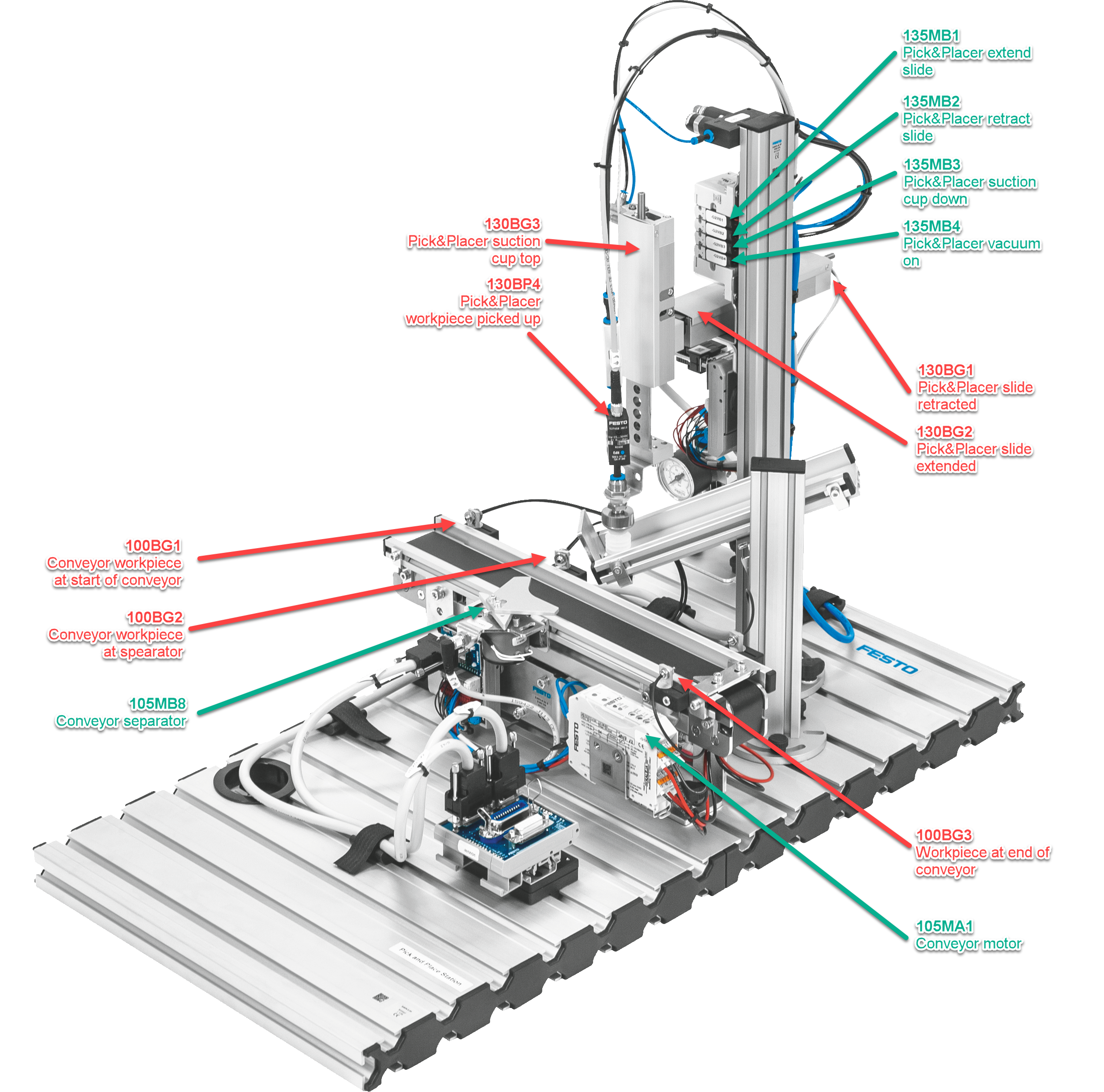
The positions of the most relevant sensors are shown below:
Info
The electrical diagram of the control cabinet can be downloaded here as a PDF
Documentation
The projects with all the comments can be downloaded as a TIA archive file (*.zap16, *.zap17 etc.) from the following file.
| Name | Date | Profession | Program |
|---|---|---|---|
| Stefan Feier | 2019-2023 | automation engineer | |
| Nicolas Diethelm | 2020-2024 | automation engineer | Download ZAP16 |
| Flavio Knobel | 2020-2024 | automation engineer | Download ZAP16 |
| Kevin Kälin | 2021-2025 | automation engineer | |
| Linus Lacher | 2022-2026 | automation engineer |