Subsections of Home
Trial apprenticeship
The best machines for spray cans worldwide
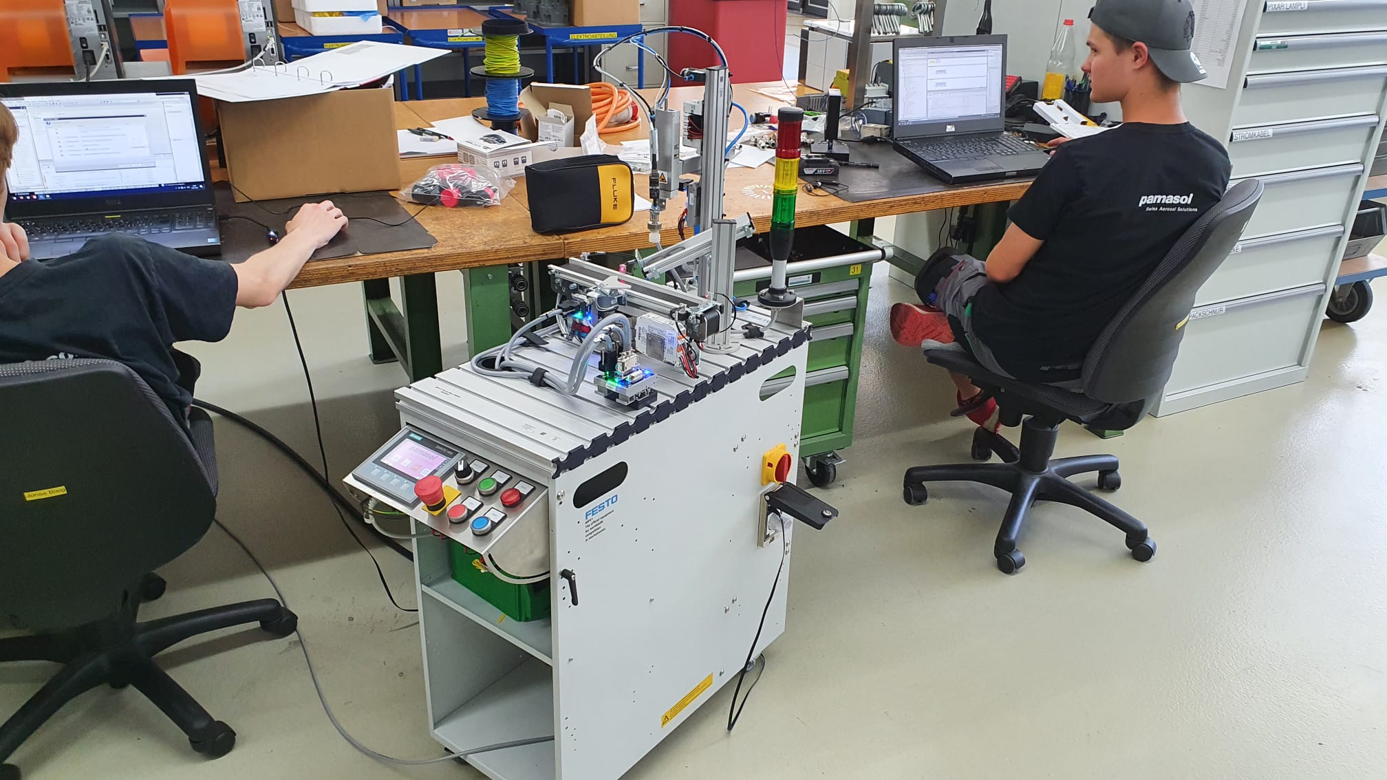
Are you interested in the profession of an automation engineer? Go ahead, sign up for a trial apprenticeship and you’ll get a first-hand experience of the fascinating world of engineering - starting with mechanical processing and assembly, through wiring of electrical components all the way to pneumatic controls and software engineering.
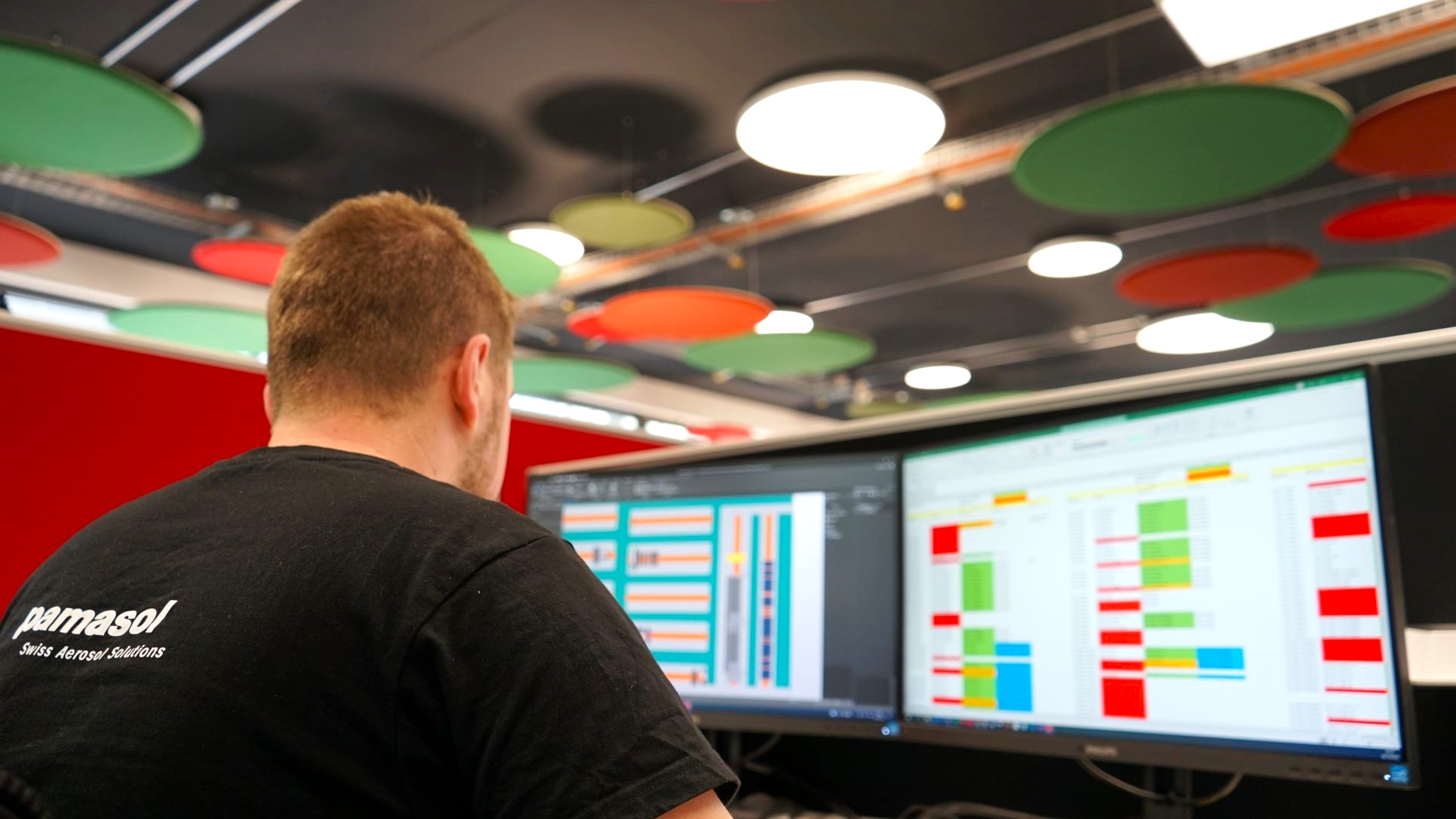
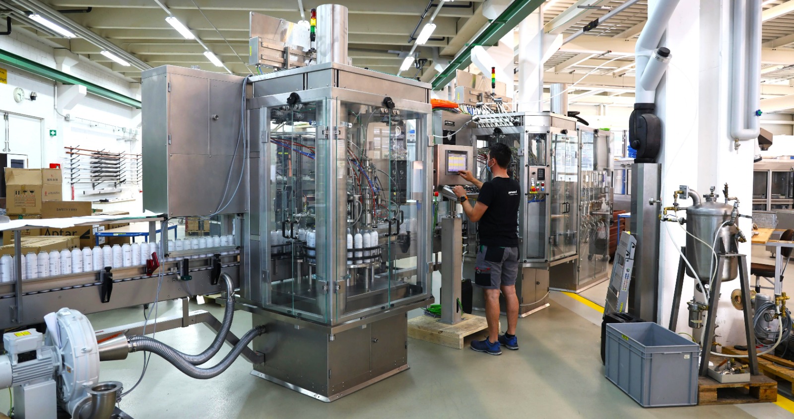
The upper picture shows a Pamasol employee testing a Macromat LB20. This is a filling and sealing machine for spray cans. While the polymechanics and metal workers are working on the mechanic and metalwork, the automation engineer mounts all the electrical components such as sensors, motors and the big touchscreen. Afterwards, the PLC (that’s the computer and thus the brain of the machine) gets programmed to bring life to the machine.
As soon as the machine is running and the customer finished his checklist, it will be shipped to the production site, for example Australia, the US or Brasil, but also Germany or Switzerland. Pamasol machines are located all around the world, producing billions of spray cans.
Fully trained automation engineers have the opportunity to visit different countries and cultures, because the machines scattered around the world are installed and serviced by Pamasol employees on site.
You probably haven’t noticed it, but you definitely had a spray can in your hand that was filled on a Pamasol machine (deodorant, color spray, oven cleaner, shaving cream, room spray, silicone spray, oil spray, …the list goes on and on).
A few answers to frequently asked questions:
Is an automation engineer a demanded profession?
Yes, automation engineers are professions in high demand and will continue to be in the future.
More and more tasks and operations are done by machines and robots. Automation engineers are needed to build the machines and program the software for it.
How long does an apprenticeship take and where do I need to go to school?
The apprenticeship lasts 4 years. During this time the apprentices will visit one to two days a week the vocational school in Arth-Goldau. If you attend the Federal Professional Baccalaureate during the apprenticeship, the school visit consists of two days a week for the entire apprenticeship.
Additionally to the vocational school you will attend inter-company professional training in the training centre Swissmechanic in Pfäffikon SZ. These trainings take a few weeks each.
What kind of advanced training opportunities are there?
There are alot of advanced training opportunities, such as the Federal Diploma of Higher Education for the automation specialist or the Advanced Federal Diploma of Higher Education for the Master in Switchgear and Automation.
The most wanted advanced trainings from Pamasol automation engineers so far are the Technician (CHF - College of Higher Education) or the study for the title Engineer (University of Applied Sciences).
If you completed the Federal Professional Baccalaureate, you can for example attend the ost.ch in Rapperswil to study for the Engineer.
How much do you earn as a fully trained automation engineer?
There are no hard and fast rules about how much you earn. Alot of factors play into that, such as work experience, function and position in the workplace or location and branch of the company.
What’s definitively in every job: If you love it and put the effort into it, it will mirror into your paycheck.
I know, the answers above do not help alot and we can’t keep interested people guessing. Following are a few numbers from the online portal jobs.ch which can give you an estimated point of reference.
Automation engineer
Electrical engineer
Video automation engineer VET
How many automation engineers did Pamasol already train?
| # | Name | Date | Profession |
|---|
| 50 | Stefan Feier | 2019 - 2023 | automation engineer |
| 49 | Jonas Bisig | 2018 - 2022 | automation engineer |
| 48 | David Bernhard | 2018 - 2022 | automation engineer |
| 47 | Joël Glaus | 2017 - 2021 | automation engineer |
| 46 | Marvin Büeler | 2016 - 2020 | automation engineer |
| 45 | Elias Kälin | 2015 - 2019 | automation engineer |
| 44 | Fabian Suter | 2014 - 2018 | automation engineer |
| 43 | Sven Faas | 2013 - 2017 | automation engineer |
| 42 | Lukas Kägi | 2012 - 2016 | automation engineer |
| 41 | Roman Feusi | 2011 - 2015 | automation engineer |
| 40 | Tom Lauper | 2010 - 2014 | automation engineer |
| 39 | Maurus Meier | 2009 - 2013 | automation engineer |
| 38 | Andreas Kälin | 2008 - 2012 | automation engineer |
| 37 | Simon Schätti | 2007 - 2011 | automation engineer |
| 36 | Silvan Donner | 2006 - 2010 | automation engineer |
| 35 | Urban Bruhin | 2005 - 2009 | automation engineer |
| 34 | Michel Keller | 2004 - 2008 | automation engineer |
| 33 | Pascal Kälin | 2003 - 2007 | automation engineer |
| 32 | Matthias Bamert | 2002 - 2006 | automation engineer |
| 31 | Roger Kälin | 2002 - 2006 | automation engineer |
| 30 | Philipp Bruhin | 2001 - 2005 | automation engineer |
| 29 | André Kälin | 2000 - 2004 | automation engineer |
| 28 | Yves Gautschi | 1999 - 2003 | automation engineer |
| 27 | Ernst Späni | 1998 - 2002 | automation engineer |
| 26 | Patrick Lechner | 1998 - 2002 | automation engineer |
| 25 | Andreas Schuler | 1997 - 2001 | electro mechanic |
| 24 | Eric Ziegler | 1997 - 2001 | electro mechanic |
| 23 | Ralph Kühn | 1996 - 2000 | electro mechanic |
| 22 | Beat Ziegler | 1996 -2000 | electro mechanic |
| 21 | Reto Inderbitzin | 1995 - 1998 | electro mechanic |
| 20 | Christof von Allmen | 1994 - 1998 | electro mechanic |
| 19 | Patrick Kühne | 1994 - 1998 | electro mechanic |
| 18 | Roman Späni | 1993 - 1997 | electro mechanic |
| 17 | Reto Bachmann | 1992 - 1996 | electro mechanic |
| 16 | Marco Kälin | 1992 - 1996 | electro mechanic |
| 15 | Andreas Knobel | 1992 - 1996 | electro mechanic |
| 14 | Martin Ruoss | 1992 - 1994 | electro mechanic |
| 13 | Marco Räber | 1991 - 1995 | electro mechanic |
| 12 | Kessler Patrick | 1990 - 1994 | electro mechanic |
| 11 | Marco Corvi | 1989 - 1993 | electro mechanic |
| 10 | Michael Kistler | 1989 - 1993 | electro mechanic |
| 9 | Patrik Diethelm | 1988 - 1992 | electro mechanic |
| 8 | Michael Manser | 1988 - 1992 | electro mechanic |
| 7 | Daniel Schätti | 1986 - 1990 | electro mechanic |
| 6 | Oskar Mäder | 1985 - 1989 | electro mechanic |
| 5 | Edgar Pfister | 1985 - 1989 | electro mechanic |
| 4 | Armin Zonder | 1984 - 1988 | electro mechanic |
| 3 | Peter Pedros | 1982 - 1986 | electro mechanic |
| 2 | Josef Schnüriger | 1980 - 1984 | electro mechanic |
| 1 | Reto Hegner | 1978 - 1982 | electro mechanic |
Subsections of Trial apprenticeship
Building a railway lamp
The fusion of mechanics and electronics
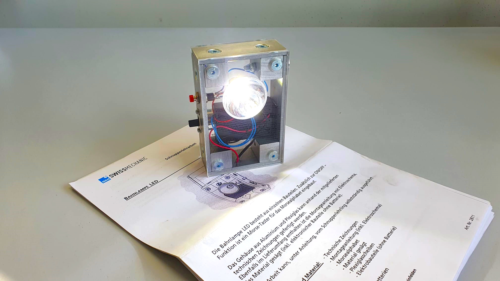
During your apprenticeship you will build a railway lamp with aluminum and acrylic glass parts. In addition to that, electronic parts will get soldered together following a schematic, which turns it into an electric circuit.
The railway lamp is an assembly kit issued by Swissmechanic. You can take the lamp home after the trial apprenticeship.
Additionally to the railway lamp, you’ll get an authentic insight into our daily work and all its exciting challenges.
Control cabinet plug board
Drawing and wiring schematics
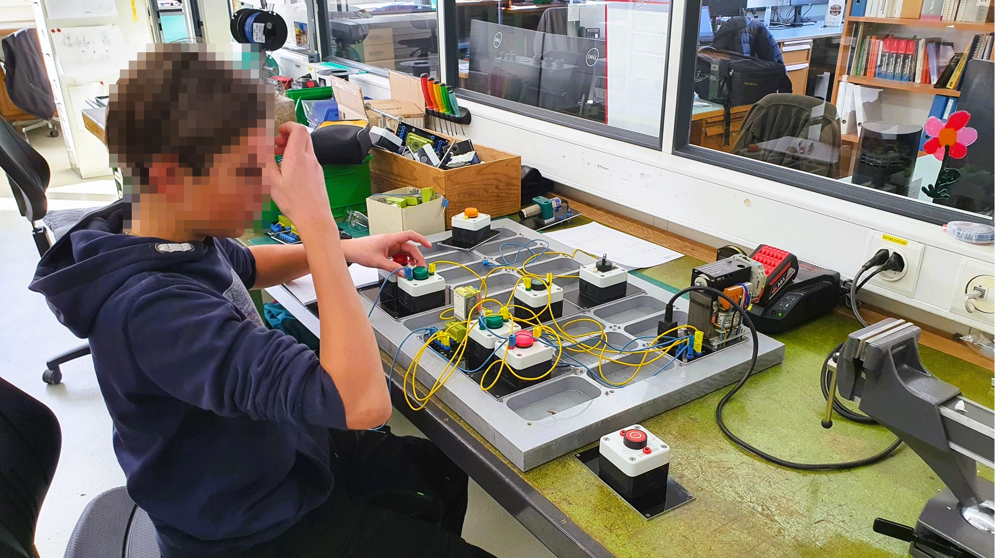
One of the most important tasks of an automation engineer is the planning and wiring of a control cabinet. These control cabinets can be the size of a shoebox, but also as big as four big closets put together.
The cabinets are filled with complex electronics, which are connected with wires. If one the hundreds of wires is connected incorrectly, the whole machine won’t work. In the worst case, parts could get damaged or destroyed, some of them costing as much as a car.
Because of this, full concentration and attention is needed when drawing these schematics. Work like this needs practice - and that’s exactly what we are doing with this excercise.
Drawing schematics with Capital™ Electra™ X
In a professional workspace schematics are drawn on programs such as EPLAN P8, Zucken E3 or WS-CAD
For the following project we recommend using the easy-to-use CAD Capital™ Electra™ X from Radica Software and Siemens. The basic functions, all of them free to use, cover everything needed for the occasional use. Additionally, you don’t need to install any software since it runs on your internet browser.
Standards for drawing schematics
How you draw a schematic and especcially how the symbols need to look is standardized. This has the advantage of having schematics which look the same all over the world and being easy to read for professional electricians.
The standard for these symbols is called IEC 60617. The most relevant symbols are found on wikipedia under the following links:
Don’t worry, you won’t need to know all of these from the beginning. There’s plenty of time during the apprenticeship.
Excercises
Info
The schematic with the excercises can be imported here as a Capital™ Electra™ X template. If you don’t want to work online with Capital™ Electra™ X can download the PDF here.
All excercises are built in the same style. On the top left corner is a description with recommended parts. The 24VDC potential is drawn too. On the top is the plus, on the bottom the minus.
The parts can be placed between plus and minus. Following is the excercise 1 as an example.
Template excercise 1

Sample solution excercise 1

Electronics project
Programming robots for automation engineer apprentices
In combination with professional school, inter-company professional trainings at Swissmechanic and practical jobs at aerosol machines for customers around the world, automation engineer apprentices at Pamasol also work on projects which focus on a certain topic.
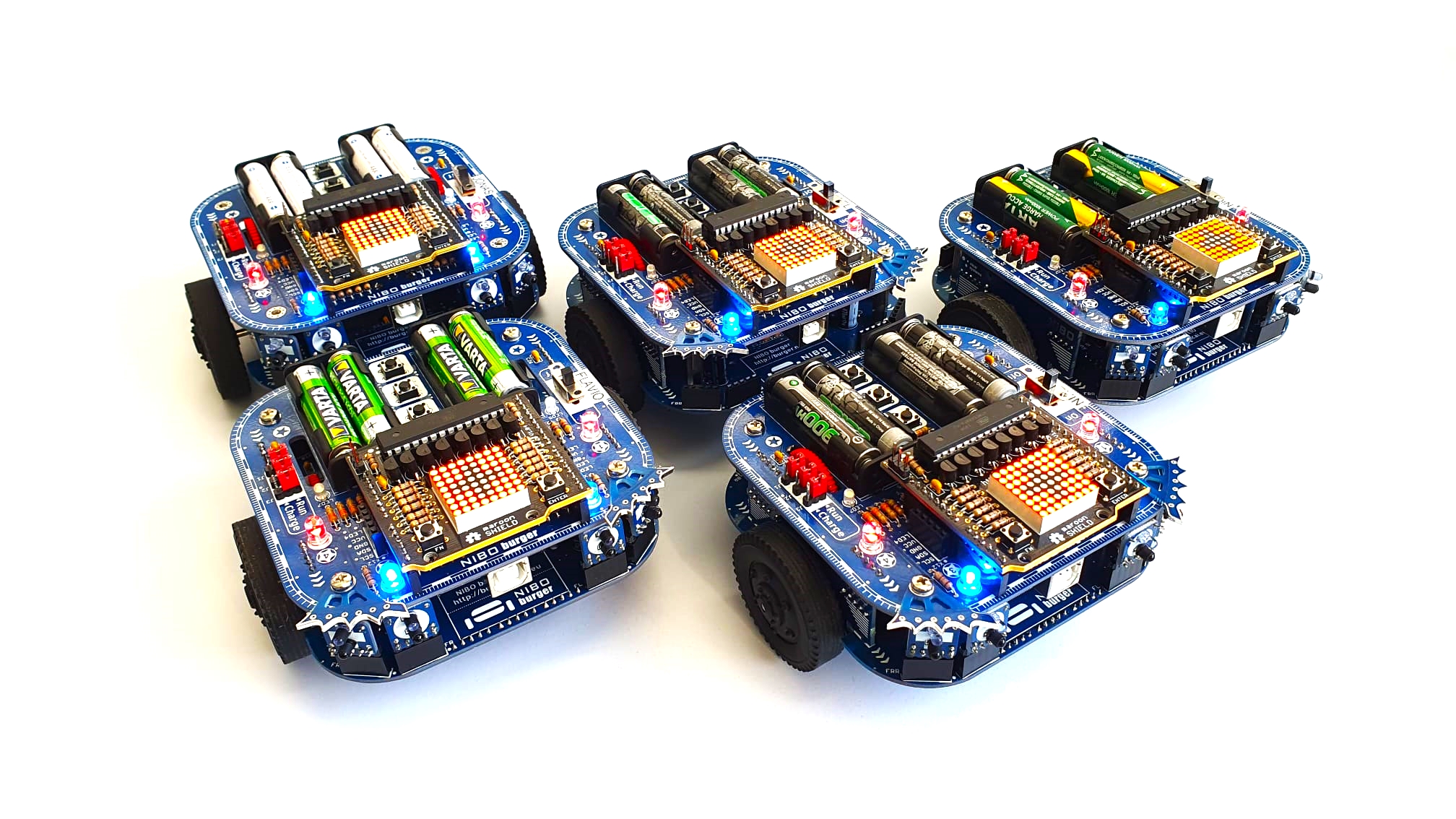
NIBO Burger represents the electronics project of the apprenticeship. It consists of a small robot which will be assembled, soldered and programmed in the standard language C by the apprentices.
The scope, including any and all datasheets and Wiki articles, are written in english. After the assembly and functionality test the apprentices will get an introduction in programming with C. The highlight of the project consists of the following «master tasks».
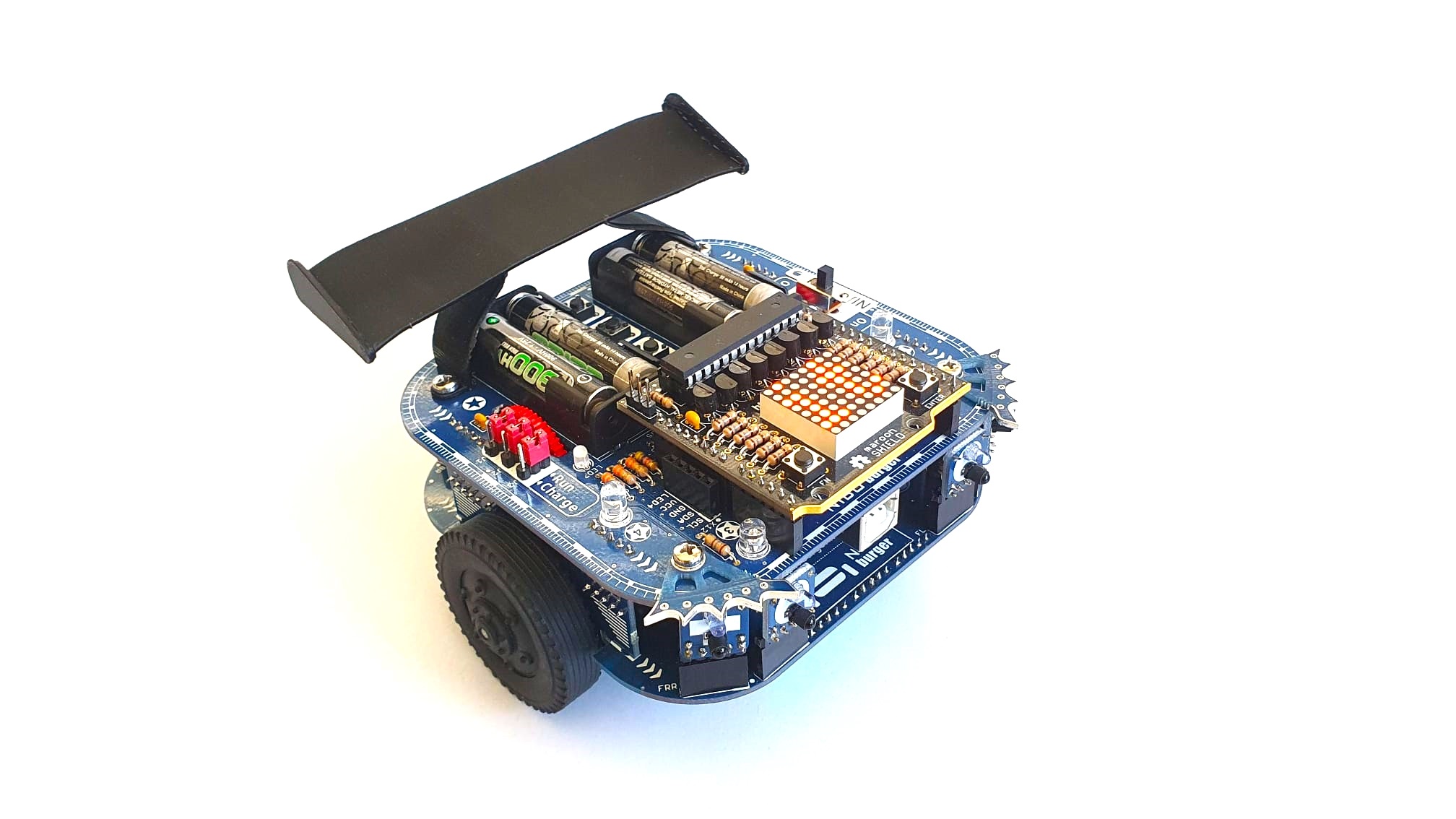
As a bonus excercise the robot will get visual upgrades made with 3D printed parts. See below a rear spoiler as an example.
A) Round trip
The robot has to drive exactly 1.5m forward, turn 180° and return to his home position. To make this excercise work, the odometry sensors of the wheels need to be read out and compared. Based on this the PID controlled motors turn accordingly.
Excercise round trip (Nibo01_V1.0.pdf)
B) Fraidy cat
The front of the robot has built-in IR bricks. These are infrared sensors which can detect obstacles. In this excercise, the robot has to avoid these obstacles.
Excercise fraidy cat (Nibo02_V1.0.pdf)
C) Follow me
Contrary to excercise B, in excercise C the robot doesn’t have to avoid obstacles but instead follow them. In this case the human hand.
Excercise follow me (Nibo03_V1.0.pdf)
D) Colour detection
With the RGB (red-green-blue) coloursensors the basic colours black, white, red, yellow, green and blue have to be detected and displayed on the built-in display. The display runs independently with a separate microcontroller. The microcontroller of the robot communicates with the microcontroller of the display by UART.
Excercise colour detection (Nibo04_V1.1.pdf)
E) Rabbit warren
In the supreme discipline the robot has to follow a black line on the ground. The line gets detected with sensors which in turn control the motors.
Excercise rabbit warren (Nibo05_V1.0.pdf)
Documentation
The elctrical parts, in combination with the soldered circuits and the program, get summraized in a written documentation by the apprentices. The following PDFs can be downloaded for a later reading.
| Name | Date | Profession | Documentation |
|---|
| Marvin Büeler | 2016-2020 | automation engineer | Download PDF |
| Joel Glaus | 2017-2021 | automation engineer | Download PDF |
| David Bernhard | 2018-2022 | automation engineer | Download PDF |
| Jonas Bisig | 2018-2022 | automation engineer | Download PDF |
| Stefan Feier | 2019-2023 | automation engineer | Download PDF |
| Nicolas Diethelm | 2020-2024 | automation engineer | Download PDF |
| Flavio Knobel | 2020-2024 | automation engineer | Download PDF |
| Kevin Kälin | 2021-2025 | automation engineer | |
| Linus Lacher | 2022-2026 | automation engineer | |
Automation project
Programming a Pick&Place robot with a Siemens PLC
Aside from vocational school, inter-company professional training at Swissmechanic and practical work on aerosol machines for customers around the world, automation engineer apprentices at Pamasol also work on projects which focus on specific parts of the education.
The Pick&Place robot represents the PLC automation project of the education. It consists of a pneumatic claw from Festo Didactic.
The robot is controlled by a Siemens ET200SP PLC (programmable logic controller). The PLC is programmed with the Siemens TIA Portal, where you can choose between the following coding languages:
- Instruction list IL
- Ladder logic
- Function block diagram FBD
- Structured Control Language SCL
- S7 graph AS
The apprentices create with the help of YoutTube Videos a PLC program including the visualization of a touch panel. The program places lids on containers, similarly like the aerosol machines at Pamasol. Here spray cans get assembled with a valve, spray button or a cap.
Subsections of Automation project
Definition of task
Desrciption of process flow
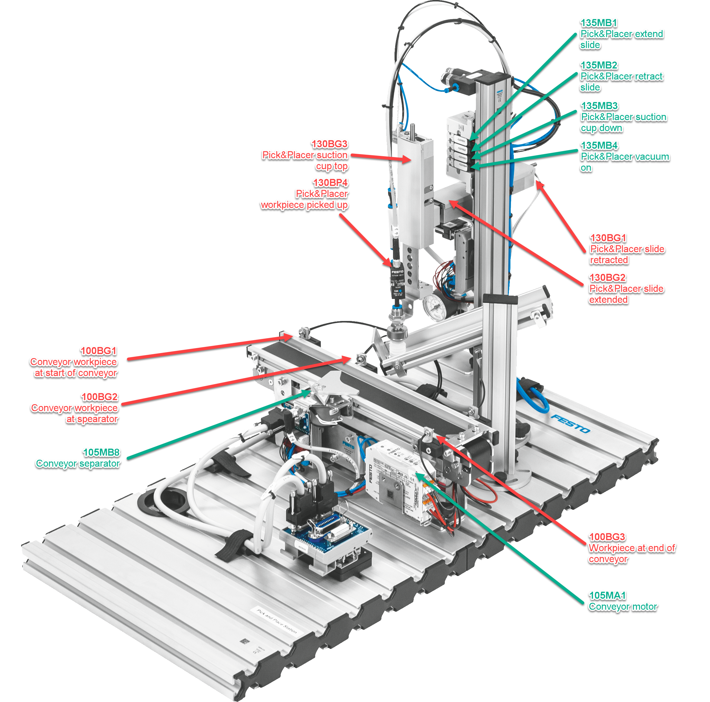
As shown in the animation above, the Pick&Placer should be programmed as follows, including the visualization of the touch panel.
- At first the Pick&Placer is retracted and the conveyor is not running
- The operator places a container on the conveyor at the inlet light barrier 100BG1 and presses the button Start.
- The container gets transported to the separator and stops there
- The Pick&Placer moves down, sucks a lid from the magazine, moves up and to the front and down again on top of the container.
- The vacuum gets released and as such places the lid on the container.
- The Pick&Placer moves to the start position.
- The separator lets the container with the placed lid move ahead.
- As sson as the container reaches the light barrier 100BG3, the conveyor stops.
The positions of the most relevant sensors are shown below:
Info
The electrical diagram of the control cabinet can be downloaded here as a PDF
Documentation
The projects with all the comments can be downloaded as a TIA archive file (*.zap16, *.zap17 etc.) from the following file.
| Name | Date | Profession | Program |
|---|
| Stefan Feier | 2019-2023 | automation engineer | |
| Nicolas Diethelm | 2020-2024 | automation engineer | Download ZAP16 |
| Flavio Knobel | 2020-2024 | automation engineer | Download ZAP16 |
| Kevin Kälin | 2021-2025 | automation engineer | |
| Linus Lacher | 2022-2026 | automation engineer | |
Brief overview TIA V16
How the development environment TIA Portal is structured
To program a PLC, you need a laptop which has the PLC programming software - in technical jargon development environment - installed.
The Pick&Place robot is equipped with a Siemens PLC which is programmed with the development environment TIA Portal. TIA is short for «Totally Integrated Automation». More information regarding this software can be found on the Siemens website.
The video explains the user interface with the views Portal view and Project view. Additionally it explains the use of the online help.
Create a new project
The PLC hardware configuration as a basis
As a first step a new PLC project will be created in the projec view. Afterwards you need to project the installed PLC from the control cabinet in the software. This will be done with the hardware configuration.
The Pick&Place robot is equipped with a SIMATIC ET200 CPU. Additionally input and ouptut modules will be added and configured.
Articel no° of the CPU for the hardware config
- Control CPU 1512SP F-1 PN:
6ES7512-1SK01-0AB0 - Safety input ET200SP F-DI 8x 24V DC HF:
6ES7136-6BA00-0CA0 - Safety output ET200SP F-DQ 8x 24V DC/0.5A PP
6ES7136-6DC00-0CA0 - Digital input ET200SP DI 16x 24V DC ST:
6ES7131-6BH01-0BA0 - Digital output ET200SP DQ 16x 24V DC/0.5A ST:
6ES7132-6BH01-0BA0 - Analog input ET200SP AI 2x U/I 2/4-Wire HS:
6ES7134-6HB00-0DA1 - Analog output ET 200SP AQ 2xU ST:
6ES7135-6FB00-0BA1
Set module parameters
Configuring central processing unit (CPU) und IOs
The modules in the device configuration are named identically as the ones in the electrical diagram. Afterwards, the address range can be assigned in the property window. Alternatively, you can open the view Device view > Device overview. All modules and address ranges are listed in table here.
The BaseUnits of the input and output modules come in light gray and dark gray. The light gray modules are powered with 24VDC. Dark grey modules can’t be powered, they are bridged to the module to the left. The following BaseUnits are used in the project:
The absolute addressing uses the direct operand (i.e. I0.0), whereas the symbolic addressing utilizes a symbol name as a substitute for the operand (i.e. CC_TB_24MainOk).
- CC stands for control cabinet. This defines the place where the part is installed.
- TB stands for the electrical part in accordance to EN 81346. In this case it is the auxiliary contact of the power supply
10TB1 - 24MainOk stands for the abbreviation of the function in Upper Camel Case. In this case it is “24VDC power supply OK”.
The variables can be added and edited in the project navigation under Devices > PLC variables. The video additionally mentions the function for importing and exporting Excel files.
Tip
The Excel file, which can be used to import the PLC tags, can be downloaded here
Set HMI parameters
4 inch touch panel Siemens KTP400 Comfort
HMI stands for Human-Machine Interface. This is the touch panel, with which the operator controls the machine.
Add the HMI under Devices > Devices and networks. It is the KTP400 Comfort panel from Siemens with the type number 6AV2124-2DC01-0AX0.
Profinet stands for Process Field Network. It is a common protocol in the industry which uses TCP/IP Standards As such, the communication between PLC and HMI works similar to the internet (IP stands for Internet Protocol). Each member of the network gets a unique IP address - the Profinet address. Each address in the projetc can only show up once.
- Profinet address HMI 155PH1:
192.168.10.5 - Profinet address PLC 20KF3:
192.168.10.10
PLC simulation
Emulate CPU and HMI for tests without hardware
With the help of SIMATIC S7-PLCSIM the Pick&Place control can be simulated and tested without any hardware components added.
The video shows the simulation of the PLC and the touch panel. Emulating means recreating the functions of a computer with another device.
To be able to emulate a PLC or an HMI, you need to select the component in the Project navigator under Devices and click on the icon Start simulation in the smybol menu.
Afterwards the preferred blocks get loaded. These can be tested almost in the same fashion as with a hardware-based PLC. For example with the Monitor on/off function or with a SIM table.
Not that important here, but for other projects: You can’t load protected blocks in the simulation. If they exist in your project, you first need to enable the access for them.
Load program
Download program from PC to PLC and HMI
To load the program from the TIA portal into the PLC. In a first step, click under devices on Devices & networks, where you can display the IP addresses.
- CPU 1512SP F-1 PN:
192.168.10.10 - Touch panel KTP400 Comfort:
192.168.10.5
In a second step you need to give the laptop, which is in the same network, a static IP address. In Windows in the adapter options choose the address 192.168.10.99 for the Ethernet port.
Select the symbol Load in device in the toolbar to load the program in the PLC.
Since we are using a Safety Integrated PLC, both safety modules 20KF5 (inputs) and 20KF6 (outputs) need to be identified. You need to assign a Profisafe address.
On the HMI, click Settings > Transfer > PN/IE > Properties… > PN_X1 > Specify an IP Address > 192.168.10.5 to set the IP address. Additionally you need to click on Load in device.
Create program
First program for Pick&Place robot
To move the horizontal axis of the robot, creat a program in Main [OB1]. Use ladder logic with the following in- and outputs.
| Description | Symbolic address | Absolute address |
|---|
| Pick&Placer HMI Start (160SF3) | PIPL_Pa_SF_Start | E1.1 |
| Pick&Placer extend carrier (125MB1) | PIPL_MB_CarrierExtend | A0.4 |
| Pick&Placer retract carrier (125MB2) | PIPL_MB_CarrierRetract | A0.5 |
| Pick&Placer HMI Stop (160SF4) | PIPL_Pa_SF_Stop | E1.2 |
| PLC Clock 0.4s (2.5Hz) | ME_PLC_Clock_0.4s | M0.2 |
| Pick&Placer HMI LED Start (160SF3) | PIPL_Pa_PF_Start | A1.2 |
| Pick&Placer signaling column green (130PF1) | PIPL_SC_Green | A0.1 |
Designing HMI
Designing a link between human and machine
The HMI (Human Machine Interface) 155PH1 consists of a KTP400 Comfort panel from Siemens. 400 stands for the screen size, which in this case is 4.3". The resolution is 480 by 272 pixels.
For comparison: a Samsung Galaxy S22 smartphone with a 6.1" display has a resolution of 1080 x 2340 pixels. Regarding the design we are a bit restricted, but you can create a nice and clear design nevertheless, to facilitate the usage of the robot for the operator.
Click on the HMI 155PH1 in the Project navigation to create a template with Image management > Templates. In the course of the tutorial 3 images based off the templates will be created:
Image_1 - OverviewImage_2 - MessagesImage_3 - Switches etc
The images and displays can be switched with buttons (click > action). The data exchange between PLC and HMI is managed by the data block DB122.
Next to the signal lamp text list, create a signal lamp called graphics list.
HMI alarms
Displaying HMI messages on the touch panel
An error which illuminates the red lamp exists already in Main [OB1], but we don’t have a message for this error. The lamp acts as a centralised error. It gets generated in network 7, which has the following variables.
| Description | Symbolic address | Absolute address |
|---|
| Pick&Placer Carrier extended (120BG2) | PIPL_BG_CarrierExtended | E0.5 |
| Pick&Placer Carrier retracted (120BG1) | PIPL_MB_CarrierRetracted | E0.4 |
| Pick&Placer Carrier extend (125MB1) | PIPL_MB_CarrierExtend | A0.4 |
| Pick&Placer Carrier retract (125MB2) | PIPL_MB_CarrierRetract | A0.5 |
| Error active | ErrorActive | M100.0 |
To give the operator specific information of a problem, Siemens has the function HMI messages. It handles the messages and the display of them on the touch panel.
To give the HMI messages, you need to create a Data block DB with the name HMI_messages, type Global-DB and number 120. In a second step create a data structure which consists of 3 structs of 1 word each (1 word = 16 bit), while the structs stand for Error, Warnings and Messages.
- Static
- Error (Struct)
Hcyl_not_extended (Bool)Hcyl_not_retracted (Bool)
- Warning (Struct)
- Message (Struct)
In a next step click in the project navigation of 155PH1 on the menu HMI messages. Choose Bit messages in the tabs and type in the following mesaages. With this you link the messages on the HMI with the program.
| ID | Message | Class | Trigger variable | Trigger bit | Trigger address |
|---|
| 1 | Horizontal cylinder not extended | Errors | Errors | 8 | %DB120.DBX0.0 |
| 2 | Horizontal cylinder not retracted | Errors | Errors | 9 | %DB120.DBX0.1 |
In the last step create an image with a Message display.
Structure program
Dividing OB1 in separate subprogrammes
The OB1, in which the program resides, can be divided into 3 FB's:
FB1 01-GeneralFB2 02-General_Pick&PlacerFB3 03-Cycle_Pick&Placer
With this the programm can be divided into small subtasks, which makes the program clearer. Additionally recurring functions such as moving the axis can be programmed once and reused again and again - which corresponds to the DRY principle.
| Blocktype | Short | Features |
|---|
| Organization block | OB | - Link between OS and program
- Graduated priorities (1 to 28)
- i.e. OB1, OB120
|
| Function block | FB | - Parametrable (with memory)
- IN, OUT, INOUT, STAT, TEMP
- Usage of instance-DB. Replace actual parameter Formal parameter.
|
| Function | FC | - Gives return value of calling functions
- Parametrable, but no(!) memory
- i.e. mathematical functions
|
| Data block | DB | - Global data storage
- Local data storage (Instance-DB)
|
C-Sharp project
Programming a calculator as a portable *.exe file in C#
Aside from vocational school, inter-company professional training at Swissmechanic and practical work on aerosol machines for customers around the world, automation engineer apprentices at Pamasol also work on projects which focus on specific parts of the education.
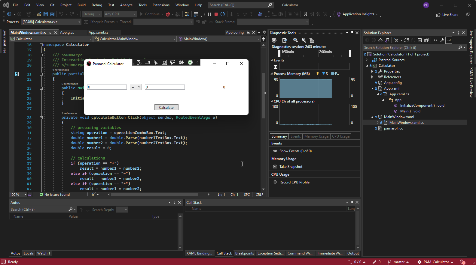
PAM-Caluclator represents the C#-project of the education. Its purpose is to introduce the apprentices into the world of object oriented programming.
With the help of Visual Studio IDE (Integrated Development Environment) a windows calculator will be programmed in C#. The calculator can add, subtract, multiply and divide two numbers. If divided by zero, the calculator will show a warning:
The created Exe-file can be executed on a PC with Windows OS.
There will be one variant made in Winforms and one in WPF. Afterwards, both variants will be compared.
Support
Getting best customer support
The machine is down, red LEDs everywhere (or nowhere), operators and managers are looking at you, expecting to fix the issue in no time.
At such a moment it is important to remain calm, analyze the situation and if necessary, contact the product support or after-sales team of the machine manufacturer.
This chapter describes how to get efficient and quick support by Pamasol After-Sales.
Subsections of Support
Prepare inquiry
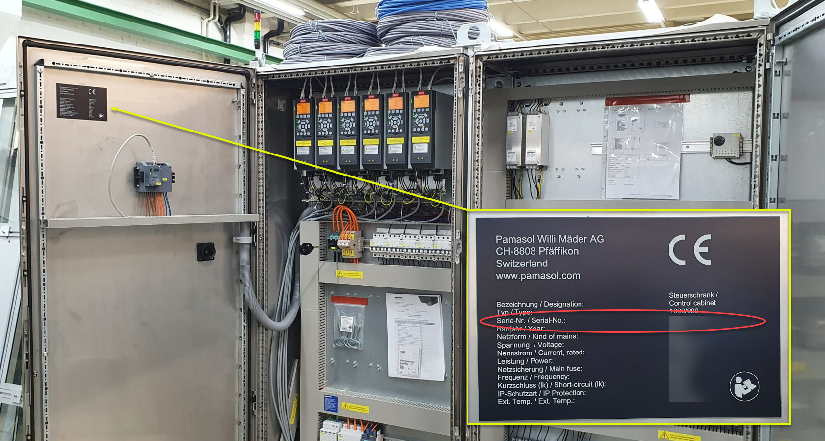
In a first step the after sales team member needs to know the serial number of the affected machine. In case of an electrical or software issue, it can be found in the main control cabinet on the most left door inside. See image below. An example for a serial number could be 12345-A1.
In a second step try to describe the error or malfunction. You should also ask yourself or your team mates the following questions:
Do you see any error messages or warnings on the HMI? Does a red or yellow LED light up on a control panel or a stack light?
How does the machine behavior differ from normal production? Does the machine not run at all or with limited functionality?
At what time did the error occur? Did it happen for the first time or has the issue been existing before already?
Has something been changed prior to the error occurrence? For example, was there a changeover, centerlining, servicing, shift change, recipe change?
Have you been in contact with the after sales team regarding this machine or this issue in the past already?
Has some troubleshooting been performed already? If so, what has been tested or checked?
Is Pamasol up to date regarding hard- and software or have some modifications been done without involving Pamasol? For example a wiring change in the control cabinet or a sensor replacement.
Can photos and videos be provided along with the error description?
Remote servicing
Let a software engineer check your machine remotely
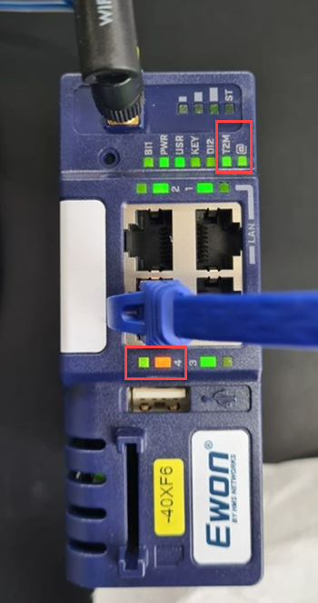
Most Pamasol machines are equipped with a secure industrial remote access device. In many cases it is a blue colored unit with the label “EWON” or “VIPA” that can be found in the main control cabinet. The following picture shows the modem which acts as a VPN router.
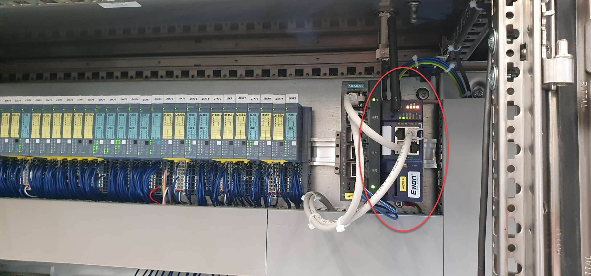
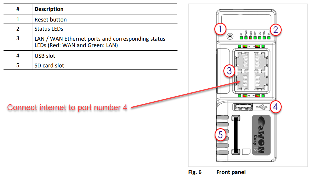
Locate this device in your control cabinet and provide internet connection via Ethernet cable if it hasn’t been done already. The RJ45 cable with internet connection needs to be connected to port number 4, which is the WAN port, as shown below.
Some modems come with a 2 position knob rotary switch, where internet access can be switched on and off hardware wise. Check if it is switched on.
Following LEDs need to light green:
- PWR = Steady green
- USR = Blinking green slowly
- T2M = Steady green
- @ = Steady green
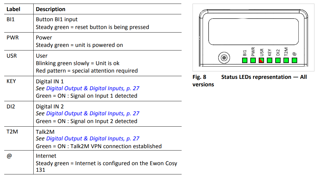
The image below shows a modem that connected successfully. There is an internet connection (@) and it was able to register at the server (T2M). The orange LED below the RJ45 port lights up constantly whereas the green LED lights up almost all the time (short interruptions that visualize the communication).
Firewall settings
Typically, your IT department needs to do nothing for using the modem. The VPN tunnels are initiated by the router and use only outgoing connections. No incoming connections are made, so no ports need to be enabled in your corporate firewall for incoming connections. In addition, it is designed to be minimally intrusive by using outgoing ports that are usually already enabled (HTTPS port 443 or UDP port 1194).
See also the PDF-file “FAQ - Remote Access” for further explanation.
Info
If there are any connection issues (and therefore T2M does not light), it is reccomeneded, whitelisting URL *.talk2m.com by your IT department.
Tip
If the IT department does not provide internet connection via company network, a GSM modem can be used as well. In this case the company network and the machine are strictly separated.